EARTHING WIRE and SURGE ARRESTER

Q.Why we are using both earthing wire on top of tower and again surge arrester in substation?
A.              Generally there are two types of lightning one is direct lightning and indirect lightning. Direct ligtining can be diverted to earth by using earth wire on top of power line so that power line was in safe condition. But there is another type of lightning called indirect lightning which cannot  be arrested by using earth wire or top earth poles because it will form on power line directly as clouds are moving on top of power line. It can be diverted only through surge arrester or lightning arrester.

                     
Preparing earth pit for system earthing by using GI pipe and coal,salt mixture (India).

DIFFERENT TYPES OF CIRCUIT BREAKERS...


MCB   -normal switch,when fault(short) occurs it will trip.
MCCB  -metal conduit circuit breaker.
RCCB  -residual current circuit breaker.
ELCB  -earth leakage circuit breaker.
OCB   -oil circuit breaker.
MOCB  -minimum oil circuit breaker.
ACB   -air blast circuit breaker.
VCB   -vacuum circuit breaker.
SF6   -SF6 gas circuit breaker.

BASIC LAWS


ohms law....
At constant temparature,the current flowing through any linear conductor is directly propotional to voltage applied across it.
               i propotional to v
                 I =V / R
            V = IR (temparature T constant)
As temparature increase the resistance will get decreases for metals.
Kirchhoff current law
The sum of entering currents equal to sum of leaving currents at a node or sum of currents at a node is always zero or sum net rate of flow of charge at a node is zero.
Kirchhoff voltage law
The sum of voltages in a loop is zero or sum of voltage rise is equal to sum of voltage drop in a loop.
 

power

Power is nothing but rate of doing work,that is nothing but joule per second.If one joule of work can be done in a second it can be defined as one watt.
                       watt = energy / time
                              = joule / second. 
                           we can write it as
                              = (joule / charge) * (charge / second)
                              =      volt             * current
             so power can be defined as volt*current, it can be called as watt.
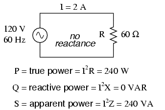
In dc supply system we can say power as watt only because it has no power factor problem which is present in ac supply system.

In ac supply system there is a phase difference between voltage and current.depending upon load i.e. capacitive , resistive,inductive loads it can be varied as leading, unity,lagging power factor.
                             power
                                 1.active power.
                                 2.reactive power.
                                 3.apparent power.
1.Active power :It is the product of ac voltage, current magnitude(average values not rms )values and cosine angle of current and voltage waves.
                          P=VI cos ∅ , unit = watts
2.Reactive power:It is the product of ac voltage, current magnitude(average values not rms )values and sine angle of current and voltage waves.
                          Q=VI sin ∅ , unit= var
3. Apparant power:It is the product of ac voltage , current magnitude(average values not rms).
                      
                           S = VI ,unit , unit = volt amp


potential difference or voltage

Potential is nothing but work done to move a charge from infinite point to a particular point.potential difference is nothing but work done to move a charge from one point to another point.There is a lot of difference between these two.

Let us assume that point C is at zero potential,In order to move unit charge from A to C we need  10 volts,In order to move charge from B to C we need 6 volts,so voltage between A&B is 4 volts.  potential difference or voltage can be defined as work done per unit charge.
                                     potential difference = work done / charge.
     The unit of voltage is "volt". one volt is defined as one joule of energy required to move a one coulomb of charge.
                          We are moving a unit charge from A to B by doing work 4 joules,so 1 volt(4 joules/1 coulomb).
           

current

It is the flow of electrons.in metals only electrons can flow with minimum opposition,in metals we can easily take out the free electrons with minimum potential.While in case of semi conductors it is some what hard to take the valency electrons out,by adding some impurities we can improve conductivity of semi conductors.In case of insulators it was very hard to extract the electrons because of high bonding forces with nucleus.
                                                   i= q / v amps
                                          current density is nothing but ratio of amount of charge flowing through conductor to area of cross section of conductor.
                                                   j=i / A =dq / dt /A amps/sec/square meter
current flow will depend on voltage across the conductor, temperature of conductor,specific resistance of conductor,length of conductor,area of cross section of conductor.

                resistance = of  ρ * l /a
                                       where  ρ = specific resistance,
                                                              l = length of conductor,
                                                              a= area of conductor,

INDOOR SUBSTATION....


We can build the substation up to 33Kv level in a room.Reason behind this is the sufficient clerence is provided in a panel.
We don't have isolators and earth switch in indoor substation as the no sufficient place. But in indoor substation also have some interlocks. Once the breaker was in close position we cannot rack-out that.After tripping that breaker only we can rack-out just same as isolator breaker interlock in outdoor substation.
                   in order to discharge the cable or bus bar we have to rack-in the cable earthing trolley and discharge as like earth switch as in case of outdoor substation.In outdoor substations we are mostly using SF6 circuit breakers but for indoor we are using mostly vacuum and air circuit breakers as low voltage levels.
          The control voltage we are using for protection was dc voltage as we can store easily and protect the system under no power due to fault. Another important use is in case of AC transmission there is more voltage drop due to inductance and capacitance and resistance, but in DC we have only resistance drop so we can provide sufficient voltage to operate trip coils.

OUT DOOR SUBSTATION....


             There are several equipment's in outdoor substations
1. Transformer
2.Breaker
3. Isolator
4.Earth switch
5.Auto re closer
6.Wave trap
7.Pole discremency
8.Current transformer
9.Voltage transformer or capacitive voltage transformer
10.Protection relays
                                             
                                                  BUSBAR erection at outdoor substation
  The control voltage we are using for protection was dc voltage as we can store easily and protect the system under no power due to fault and in order to reduce voltage drop.

1. Transformer:
                           It is used to step up or step down the voltage levels with maintaining same power and frequency.This process is done because of reducing copper losses.
                                                                P =V' * I' = V" * i"
2. Breaker:
                          It is used to interrupt the main power supply at normal and abnormal condition as well.
3.Isolator:
                          It should be opened after opening the breaker which was connected before. The need of isolator is  for maintenance purpose of breaker and in order to protect the persons from mal-operation of breaker.
4. Earth switch:
                         For high amount of voltages,the equipment are charged and possess the charge in shutdown period also.In order to discharge the charge the charge on equipment's when maintenance work is going to do . When the line beside the dead line is in running condition then there is a emf will induce in dead line also due to induction so it is necessary to discharge the charge induced in that line with earth switch
5. Auto re closer:
                         In order to serve the load after clearing the temporary faults.We should design the scheme as 86 should not pickup for temporary faults.Then the auto re closer will check for every time period and close the breaker.
6.wave trap:
                           It is a LC low pass filter which used to allow only power frequencies and block the high frequencies like communication frequencies ( which are using for PLCC ). It is placed at entering of line and leaving of line after CVT only. And in so many substations they will be placed in only two phases out of three phases, because of we are using only two channel communication. By calculating line parameters they will decide the phases which are suitable to place wave trap.

7.Pole discrepancy:
                        For small substations we have one three phase breaker.But when going to large substations we will find three single phase breakers. when any fault occur a phase then its respective breaker is going to trip,then our auto re closer come in to picture and check the faults was temporary or permanent,if fault was temporary then breaker will get closed by using auto re closer,in case of permanent fault auto re closer will open that phase permanently.Then there is unbalance in load,so we will set time in pole discrepancy relay (ex. 2sec),then it will give trip command to remaining healthy phases also.

8.Current transformer:

                       Current transformer is also same as the power transformer with slight difference,current transformer is not used for step up or step down  of voltage levels as in case of power transformers.It is mainly used for step down the current levels. Generally in transmitting of power is done at high currents and voltages,but our ammeters and energy meters are does not with stand such high currents, on other hand protective devices like relays are also unable to with stand the high currents.
         So by step down the current with certain ratio and that value is used for protection and metering,then by multiplying with that factor we can get the real values that in line.
         So generally secondary current range is 1A or 5A. And primary current was is in order of 1000 amps.
 MAIN DIFFERENCE between POWER TRANSFORMER and CURRENT TRANSFORMER
  In power transformer primary current depend upon secondary current, but in current transformer primary current will depend upon on only load not on secondary burden or secondary current.
   note: CT secondary circuit should always in closed condition only,we should short spare core.

9.Voltage transformer or capacitive voltage transformer:
                         Potential transformer is almost same as power transformer. But used for only step down of  high voltages to 110 V (line to line).It was very low power rating which is used for only burden. As our voltmeters and energy meters and relays are unable to work with very high voltages, we step down the voltage range and use that for meters and relays and multiply with factor.
     generally secondary voltage is 110 V (line-line) where as primary voltage is of order of kilo volts.
                  capacitive voltage transformer is also similarly voltage transformer but it has construction like below  figure.The construction is like this because to measure high voltages which are not measured by normal voltage transformers. some of voltage will be dropped across capacitor C1 and remaining voltage was stepped down.The combination of capacitors and inductor acts as filter which was used to catch only communication signals and leave the power waves towards load.
                                            One of the most important factor is voltage transformer is used for only voltage measuring purpose and ordinary protection,but capacitive voltage transformer has advantage that it can also used for communication purpose between substations (as like wave traps).
  note:never short the spare cores of VT or CVT.

10.Protection relays:
                               Protection is very important for electrical machines and equipment's as they are cost very high, in order to protect those we will use the electrical quantities and estimate the abnormal and normal condition of a system,based on those values we will design our protection scheme.Some of major protections that are employed in electrical system.
                            1.over current protection.
                            2.over voltage protection.
                            3.over flux protection.
                            4.under voltage protection.
                            5.under and over frequency protection.
                            6.distance protection.


          NECESSARY INTER LOCKS FOR OUTDOOR SUBSTATION

Need of interlocks : in order to protect the system from maloperation  of skilled and unskilled labour persons.

ISOLATOR AND BREAKER:
                     Isolator should not open and close when breaker is in closed condition.Why. because  seviour amount of arc will struck between the isolator poles as there is no arc extinguisher medium and as time of opening and closing of isolator are high.

ISOLATOR AND EARTH SWITCH:
                    Isolator should close when earth switch is connected,because total charge will get down to earth as earth fault.so in order to protect from that situation we have to design interlock

EARTH SWITCH AND BREAKER:
                   Earth switch should not be closed when breaker is in closed position (for remote operation). For local operation and manual operation no necessary of this interlock (depend upon customer requirement).

DIFFERENT PROTECTIONS IN OUTDOOR SUBSTATIONS....

TRANSFORMER DIFFERENTIAL PROTECTION and RESTRICTED EARTH FAULT PROTECTION:
                                       Differential protection,protects the transformer from its internal faults only,it will compare entering and leaving currents of transformer and operate on its setting
                                       REF protection operates if any earth fault occurs inside the transformer.The principle behind this is to sum the neutral current and phase currents.

TEE DIFFERENTIAL PROTECTION:
                                        In one and half scheme substations we have three CTs connected as T section,if any fault occurs in this T section then this protection will operate.


CIRCUIT BREAKER....


We all know that breaker is switch which is going to operate under normal condition manually and abnormal condition automatically. When the high amount of current was breakup then high amount  of  arc will struck which is un desirable,so breaker also consists of arc extinguisher medium.
                                                   structure of normal power system protection
       1.Relay.
       2.Master relay or lockout relay (its code 86,it should resettled manually).
       3.Trip coil 1,2 (which are in breaker, coil 2 is used as backup coil).
       4.Close coil.
sf6 gas 400kv T shape breaker ( two interrupter)

sf6 gas filling at site after erection

Cascading two 400kv breaker in application of 765kv (India)

Grading capacitance used in breaker for inductive loads

Name plate of grading capacitance

When any fault occurs on system it is going to be sensed by relay and give trip pickups master trip relay.Then 86 will pickup and close the tripping circuit by using trip coil (both 1,2 coils),in case of any fault in coil 1 then coil 2 will come in to picture.once the fault is cleared then first we have to reset the 86 and then should give close command to close coil in order to close the breaker.

1. RELAY
2.86 or MASTER TRIP COIL.
3.BREAKER TRIP COILS.


AUTO RE CLOSER....

Mostly auto re closer will come at substations.In order to rectify power outrage for transient faults.
generally the trip circuit of breaker is going to activate for what ever the fault (temporary or permanent).Once the trip circuit was activated then the respective breaker is going to trip in order to isolate fault from healthy part, Once the breaker undergone to trip then person should give command to close circuit of breaker after the respective fault was cleared, i mean this closing process is not automatic process.
                                               If the fault is temporary then breaker is undergone to tripping mode,after clearing fault it may not close automatically,then we got power interruption.
                                            Auto re closer is an electrical device which monitor the fault condition for every time period (may be like 1 or 2 sec).generally we hear the word SHOT in case of auto re closer,once the fault occurred then breaker is going to trip without involving the master trip relay (86 lockout),then auto re closer closes the breaker after its time period,if again the fault is there in line then again breaker will goes to trip,again the auto re closer closes the breaker, and if fault is there yet then auto re closer trip the breaker permanently (considering fault was permanent) using lockout relay.the number of times auto re closer acts ac considered as shots.
                                                    
                                                    Auto re closer are generally two types, single phase and three phase auto re closer.single phase auto re closer will operate for only single phase faults. It will not operate for three phase faults. generally temporary faults are single phase faults. three phase auto re closer will operate operate for three phase faults.

Q. What is lockout relay?
A. When any fault occurs on system,relay senses and will not give trip command directly to breaker,relay will pickup the lockout relay.Then lockout will sends trip command to breaker trip coil,then breaker under goes to trip.once the lockout has pickuped the it has to be resettled by manually only,it will not resettled automatically.

CAPACITIVE VOLTAGE TRANSFORMER....

capacitive voltage transformer is also similarly voltage transformer but it has construction like below  figure.The construction is like this because to measure high voltages which are not measured by normal voltage transformers. some of voltage will be dropped across capacitor C1 and remaining voltage was stepped down.The combination of capacitors and inductor acts as filter which was used to catch only communication signals and leave the power waves towards load.
                                            One of the most important factor is voltage transformer is used for only voltage measuring purpose and ordinary protection,but capacitive voltage transformer has advantage that it can also used for communication purpose between substations (as like wave traps).

DIFFERENT TESTS TO DONE:

1.MEGGER...

2.

SYNCHRONIZATION....

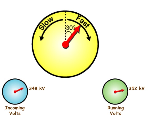
Synchronization means connecting parallelly two vector quantities which are identical. i mean two vector quantities having same magnitude and phase angles and same phase sequence and angular velocity.

Mostly synchronization comes at breaker,generator,transformer which are going to connect parallelly. The main conditions to be satisfied for parallel operation.
       1. Voltage should be equal
       2. phase angle should be equal.
       3. phase sequence should be equal.
       4.angular velocity.
 The newly connecting machine should satisfy all above conditions with already running machine.other wise circulating currents will flow between machines and they will heat up the machines grid failure may occur.
      For checking synchronization we use a device called synchroscope.


we use generally two methods called
            1.bright lamp method
                           this method is used to compare opposite phase vectors(R1,Y2 and Y1,B2 and B1,R2 etc...),when they are equally out of phase then lamb illuminates bright light,then we can connect parallelly at that time.
            2.dark lamp method
                          this method is used to compare same vectors (R1,R2 and Y1,Y2 and B1,B2) , when they are equally in phase with equal voltage then lamb become complete dark,then we connect parallelly at that time.

          DIFFERENCE BETWEEN SYNCH CHECK and SYNCHRONIZATION.....

SYNCH CHECK: When the two incoming lines are need to connect to same busbar then the BCU( bay control unit will just compare the parameters like voltage,phase angle ,phase sequence and if those are with in the limits then BCU will give close command to breaker , other wise it will not release command.
                 Generally located at substations.

SYNCHRONIZATION: When the running generator is need to connect to running line then synchronization relay will compare parameters and if satisfy then it will give command to breaker,otherwise it will give command to AVR of generator to increase or decrease voltage levels, give command to speed governor increase or decrease the frequency of generator, after matching parametrs it will issue command to breaker.
                 Generally located at power plants.


MOTOR....

Motor is just opposite to generator action,mostly the construction is same as the generator construction,so test to be conducted also mostly same as generator. Generator works on fleming right hand rule where as motor works on fleming left hand rule.

GENERATOR....

Generator is the most important device in electric field,generators are classified based on application.

GENERATORS
1. AC GENERATORS or ALTERNATORS (which have frequency).
      1.SYNCHRONOUS GENERATORS (having constant frequency)
                      1.ARMATURE ROTATING.
                      2.FIELD ROTATING.
      2.ASYNCHRONOUS GENERATORS (INDUCTION GENERATORS, variable frequency)

2. DC GENERATORS (zero frequency)                        
      1.SHUNT GENERATORS.
      2.SERIES GENERATORS.
      3.COMPOUND GENERATORS.                

at factory so many tests are going to do by manufacture

DIFFERENT TESTS are to be done at field :

1.MEGGER

2.WINDING RESISTANCE


WAVE TRAP....


Wave trap,its name indicates that it is used to trap some waves.

Q.What is the use of wave trap in electrical system,where it used?
A.Wave trap is used for communication purpose in substations.

Q.We have the telephones in these days?then what is again these communication?
A.20 years back our country was not developed in telecommunication sector.then our electrical engineers developed a system that communication can be done through our power lines.it is called power line carrier communication (PLCC).
                                  But in these days we are modifying with optical fiber inside the earth wire. it will take care of speech communication and protection.

Q.Can we transmit electrical power and communication at the same time with single conductor?
A.We can transmit,but with different frequencies.so they can be separated easily by wave trap at entrance of substation.
          Generally electrical power waves has frequency of 50 Hz,so we send our communication waves with high frequencies like 150kHz,200kHz etc..,
             Wave trap consists of filter circuit (combination of capacitor and inductor) which is used to allow only power frequency waves to electrical equipment's and stop the communication wave in to yard.


before erecting the wave trap at site (765/400 kv substation,India)
Q.Why wave trap is located at entrance of substation?what will happen if electrical equipment's receive communication waves?
A.As communication waves are high frequency (and not power frequency) they will act as harmonics towards electrical equipment's like transformer,breaker etc...,so in order to protect them we should connect at entrance (after the CVT) so that wave trap will trap the communication waves.

Q.What is the need of communication between substations?
A.If any fault in any substation,it should intimate to all connected substations to it.
  each telephone is connected to only one particular substation only.

HI-POTENTIAL TEST....


Q. What is the need of doing hi-pot test?
A. We are checking that the bus bar is capable of withstanding of high voltage are not.We also say as we are checking dielectric strength of insulation medium for high voltages.

Q. hi-pot test is limited times test,we should not do for more times, why?
A. As we do it many times ,the properties of insulation medium changes and life time decreases.But for bus bars insulation medium is air so we can do any times as air changes generally but consider about supporting structures.

Q. How much voltage should apply?
A. assume the bus rated voltage as V volts(ac rms voltage)
        The amount of AC voltage applied to cable =  ( 2* V + 1) 
Q. Why we apply 100% of voltage ,in cable hi-pot we apply only 80% voltage, why?
a.  For cables,already at factory they will do hi-pot test at 100% dc voltage,in order to protect life of  insulation medium  we will reduce applied voltage,if we do same test for third time we will decrease to 60% voltage.
                      In bus bar,the insulation medium is air,so it will replaced by fresh air so no problem for bus bars.but in case of cables the insulation medium is constant,so its property will change.

Q. Why we applying AC voltage for bus bar, but in case of cable we can apply DC voltage only?
A. The distance between the phases is some what high so capacitance between phases are low,so they will take very low charging currents ,so no problem of capacitance.
                           

PROCEDURE:

 1.Remove all external connections before doing test.
 2.Connect the remaining phases and to earth.
 3.Confirm that no other person is in contact with bus.
 4.Apply the AC voltage with using hi-pot kit.
 5.Note down the leakage current.
 6.Discharge the charge after the test.
 7.Repeat the above steps to all cores.

Q. Why we should do megger after the hi-pot?
A. To identify the insulation is same as before hi-pot or not.It was not so important for bus bars as medium was free air,but while considering supporting structures we should take in to account.

HI-POTENTIAL TEST....

Q. What is the need of doing hi-pot test?
A. We are checking that the cable is capable of withstanding of high voltage are not.We also say as we are checking dielectric strength of insulation medium for high voltages.

Q. hi-pot test is limited times test,we should not do for more times, why?
A. As we do it many times ,the properties of insulation medium changes and life time decreases.

Q. How much voltage should apply?
A. assume the cable rated voltage as Vvolts(ac rms voltage)
        The amount of DC voltage applied to cable = 80% * ( 2* V + 1) * 2 
Q. Why we should apply only 80% of voltage ,in bus bar hi-pot we apply 100% voltage why?
a.  Already at factory they will do hi-pot test at 100% dc voltage,in order to protect life of  insulation medium  we will reduce applied voltage,if we do same test for third time we will decrease to 60% voltage.
                      In bus bar,the insulation medium is air,so it will replaced by fresh air so no problem for bus bars.but in case of cables the insulation medium is constant,so its property will change.

Q. Why we applying dc voltage only for cables but in case of bus bars we can apply ac voltage?
A. The distance between the cores is very small so capacitance between cores are high,so they will take high charging currents in case of ac voltage then we cannot get exact leakage current so we calculated insulation resistance will come as low value.
                            Another main important point is as capacitance is high, ferranti effect will occur so cable will get damaged at other end of cable.

PROCEDURE:

 1.Remove all external connections before doing test.
 2.Connect the remaining cores and cable gland to earth.
 3.Confirm that no other person is in contact with cable.
 4.Apply the dc voltage with using hi-pot kit.
 5.Note down the leakage current.
 6.Discharge the charge after the test.
 7.Repeat the above steps to all cores.

Q. Why we should do megger after the hi-pot?
A. To identify the insulation is same as before hi-pot or not.

WINDING RESISTANCE....

Q.What is the need of doing winding resistance test?
A. For different types of CT 's we have different secondary resistance values which are specified on name plate details.It will mainly depend upon burden to be connected to CT and knee point voltage of CT.

Q.Can this test done by multi meter? or should we use any kit?
A. We can do by using multi meter because CT winding resistance is some what higher so multi meter probe resistance will not effect so much. For better values we can use 1amp winding resistance kit also.

PROCEDURE:
1. Isolate secondary of CT from any other winding.
2. By using multi meter measure winding resistance.
3. Repeat  the same for different taps if it has tappings.

RATIO TEST....


Q. What is the need of doing ratio test?
A. We will check the ratio according to manufacture specification.

PROCEDURE:
1. Remove all external connections.
2. Short the secondary winding.
3. Inject 25% of rated primary current by using auto transformer and loading transformer.
4.Note down the secondary current by using leakage current tester.
5. Check the ratio by dividing primary current by secondary current.
6. Repeat the same procedure for 50% , 75%  , 100% of primary current.
7. Repeat the same test for different tappings.
8. Discharge the charge after completion of test.

POLARITY TEST....

Q.What is the need of doing polarity test?
A.Polarity is very sensitive in case of differential and restricted earth fault protections,so it is necessary  to identify the polarity of CT.

PROCEDURE:
                  remove all external connections before doing test.
1.Connect analog galvanometer to secondary core winding(+ve to S1 and -ve to S2).
2.Apply dc voltage in impulse fashion ( apply and remove) to primary conductor (+ve to P1 and -ve to P2).
3.Observe the deflection in meter.
4.If the deflection is in clock wise then its polarity is correct.other wise polarity is wrong.

Q. Why we are using galvanometer not ammeter?
A.  Galvanometer only senses small currents (as we are applying 1.5 volts to primary,secondary current is low).

Q. Why we apply dc voltage is in impulse fashion,not continiously?
A. For pure dc we cannot generate time varying flux,if not transformer action will not developed.

Q.What will happen ac voltage?
A. pointer in galavonameter will continiously oscilates which we cannot idetify the polarity.

INSULATION RESISTANCE...

Q.  What is the need of doing this test?
A.   We all know the winding in transformer (either primary or secondary) should be isolated from the ground and primary and secondary winding should be connected magnetically but not electrically. so transformer should maintain some insulation from ground and other winding, and also CT should maintain insulation between cores(in case of multi core CTs).
               always apply 500v  for secondary to earth and core to core .
Q. Why we should only apply only 500v ?    
A.The secondary circuit of CT was designed to withstand only low voltages up to 500 volts.If we apply high voltages it will destroy (insulation problem).


  •        while doing the megger, specify the temperature 
                  why,because  
                                       resistance ∝ 1 / temperature.

PROCEDURE :
   Remove all external connections before conducting the test.
  1.  Connect the positive lead of megger to primary conductor and negative lead to earth,apply megger voltage for one minute and note down the reading.
  2.  Connect the positive lead of megger to  secondary winding and negative lead to earth,apply megger voltage for one minute and note down the reading.
  3.  Connect the positive lead of megger to primary conductor and negative lead secondary winding,apply 500 voltage for one minute and note down the reading.
  4.  Connect the positive lead of megger to core 1 and negative lead remaining cores, one by one (in case of multi core CT),apply 500 voltage for one minute and note down the reading.


WINDING RESISTANCE TEST....

Q. What is the need of doing winding resistance test?
A.  In order to identify any short circuit between winding turns,estimate the copper loss of machine as it will heat up the machine.

Q. We are using separate kit for finding resistance instead of using multi meter,why?
A. By using multi meter we cannot get prescribed value in micro ohms and we know that winding resistance value is vary low so multi meter probe wires resistance also added into winding resistsnce of transformer.
   by using multi meter we are applying voltage and so that current is flowing,so we are finding resistance.
     But by using TRM (transformer winding resistance) kit we are injecting DC current and measuring voltage drop across only winding (in this case probes will not included) voltage.so by dividing voltage with current internally we will get DC winding resistance,in order to get AC resistance we should multiply with factor 1.6 (because of skin effect) .
           
             voltage leads should be inside current leads should be out side.....
Q. what will happen if those leads are inter changed?
A. Value we get is not exactly correct,because for low resistance measurement ammeter-voltmeter method is suitable (having low loss in meter).For measuring high resistance voltmeter-ammeter method is suitable. As we are measuring low values it is advisable to connect voltage leads inside the current leads.
Q. Why we should do this test at last?
A.  We are injecting 10 - 100 milli amps,so the core will be in magnetization mode after doing the test for some time,so remaining test results will not be accurate.

PROCEDURE:
1.Remove all external connection before conducting test.
2.Connect the all wires of kit as per above diagram and connect the grounding wires also.
3.Inject the 10 milli amps with kit.
4.Apply for one minute.
5.Note down the resistance value shown by kit.
6.Discharge the charge in winding through kit or to ground by using external earthing rod.

what we got the value is DC resistance,multiply with factor 1.6 to get AC resistance....


INSULATION RESISTANCE ....

Q. What is the need of doing insulation resistance test for bus bar?
A. In order to verify the electrical isolation between phase to earth,phase to phase.


  •        while doing the megger, specify the temperature 
                  why,because  
                                       resistance ∝ 1 / temperature.


PROCEDURE:

1. Remove all external connections before conducting test.
2. Connect remaining phases (which are not going under test) to earth.
3. Confirm that no person in contact with cable are at other end.
4. Apply megger voltage to phase which is being under test.
5. Discharge the charge after test.
6. Repeat the same procedure for remaining phases (ex ..Y,B ).

BUS BAR...

Bus bar is a electrical conductor where voltage should be maintained constant and current density will changed according to load tapping.In feeder the voltage will change and current will remain constant as no intermediate tapping is there.
                   
DIFFERENT TESTS...

                               insulation resistance test should be done before hi-pot and after hi-pot.

all aluminium conductor

aluminium conductor steel re-in-forced conductor

aluminium pipe conductor


1.INSULATION RESISTANCE TEST....

2.HI-POTENTIAL TEST....

VECTOR GROUP TEST....

Q. What is vector group?
A.  In three phase transformers we can connect the winding in different fashion.Based on the wingding connection, we will determine vector group.generally vector group is indicated on the Name Plate of transformer by the manufacturer.The vector group teaches us about the phase difference between the primary and secondary sides.The Determination of vector group of transformers is very important before connecting two or more transformers in parallel. 
                     If two transformers of different vector groups are connected in parallel then phase difference exist between the secondary of the transformers and large circulating current flows between the two transformers.

Q.What is the need of doing this test?
A. We just confirming the the vector group given on name plate details is correct or not.

PROCEDURE OF TESTING...

    1. Give three phase supply to primary of the transformer .
    2. Short the primary and secondary R phase externally.
    3. Apply three phase voltage to the primary of the transformer (415 volts) . 
    4. Measure the voltages that we need . 
    5. Check the equations by using values.
     
Remove all electrical connections while doing test for better results.............


RATIO TEST....

Q. What is the need of doing ratio test?
A. We will check the ratio according to manufacture specification.

PROCEDURE:
1. Remove all external connections.
2. Open the secondary winding.
3.Apply voltage(available voltage like230 V) primary point or tan delta point to earth point which was removed from earth.
4.Note down the secondary voltage by using multi meter.
5. Check the ratio by dividing primary voltage by secondary voltage.
6. Repeat the same test for different tappings.
7.Discharge the charge after completion of test.

INSULATION RESISTANCE TEST....

Q. What is the need of doing insulation resistance test for cables?
A. In order to verify the electrical isolation between core to earth,core to core.


  •        while doing the test, specify the temperature 
                  why,because  
                                       resistance ∝ 1 / temperature.

PROCEDURE:

1. Remove all external connections before conducting test.
2. Connect the cable gland and remaining cores (which are not going under test) to earth.
3. Confirm that no person in contact with cable are at other end.
4. Apply megger voltage to core which is being under test.
5. Discharge the charge after test.
6. Repeat the same procedure for remaining cores (in case of multi core cables).

POWER CABLES....

Cables are very important why,because once they are installed under earth it is difficult to replace them if any fault occurs so maximum care should be taken for them.
             Generally different cables are available based on their operating voltage levels and cores.like 3.3kv,6.6kv,11kv,33kv,66kv etc and single core and multi core.

DIFFERENT TESTS....
        
                             insulation resistance test should be done before hi-pot and after hi-pot.

single core cable at site before erection.


CURRENT TRANSFORMER....

400 kv, 3000/1A CT at site after erection

CT junction box
        Current transformer is also same as the power transformer with slight difference,current transformer is not used for step up or step down  of voltage levels as in case of power transformers.It is mainly used for step down the current levels. Generally in transmitting of power is done at high currents and voltages,but our ammeters and energy meters are does not with stand such high currents, on other hand protective devices like relays are also unable to with stand the high currents.
         So by step down the current with certain ratio and that value is used for protection and metering,then by multiplying with that factor we can get the real values that in line.
         So generally secondary current range is 1A or 5A. And primary current was is in order of 1000 amps.
 MAIN DIFFERENCE between POWER TRANSFORMER and CURRENT TRANSFORMER
  In power transformer primary current depend upon secondary current, but in current transformer primary current will depend upon on only load not on secondary burden or secondary current.
CT at 765kv site at India

working at CT secondary box in site (India)

      DIFFERENT TESTS OF CURRENT TRANSFORMER....

1. INSULATION RESISTANCE...

2.POLARITY...

3.RATIO TEST...

4.WINDING RESISTANCE...

5.KNEE POINT VOLTAGE TEST...(for PS class only)